Sensors to Measure Bending Forces in Structures
For our workshop on "Building and Testing Structures" it was necessary to find ways to gather data from non destructive tests on structures that were built by students. In order to do this we used an off the shelf CMA force sensor to apply and measure forces to the structures. We then wanted to measure how much certain structural members in the towers bent under that applied force. In order to measure this bending it was necessary to construct special sensors. Since it is easy to make any analog electrical device work as a sensor with Coach Software and any interface (i.e. CoachLab, ULAB, TI-CBL, LabPro, etc) it is not a hard or time consuming task to construct special sensors.
A transducer that can respond to bending force is already available on the market. It is called a "Flex Sensor" and is available from many electronics and robotics websites for about $10.00 each. This device was originally designed to be used in gloves and other feedback devices that could gather information from wearers for artificial reality.
![]()
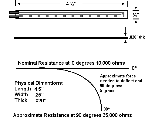
The sensor (shown above at almost real size) is simply a variable resistor that changes its resistance in response to how much it is bent. The way that the device works is based on its construction.
| The way that the device works is based on its construction. The sensor has a backplane of a thin plastic polymer that can easily bend. On top of this polymer is a layer of carbon that forms a resistor (which connects between the two metal terminals on the left side). On top of the carbon are equally sized and spaced squares of metal which are glued in place at their centers to the backplane. When the device is bent the spaces between the metal plates grows larger and thus the amount of carbon resistor shorted out by each metal square is reduced. When that happens the resistance of the sensor goes up. The response of the sensor is very linear over its flexible range. The sensor can only reliably indicate bending in one direction (into the page as it is pictured here). Multiple sensors can be used to record bending in multiple directions. |  |
To connect the sensor to CoachLab we simply soldered cables to the sensors and placed 4-mm banana jack connectors on the other end. CoachLab II has 4-mm banana jack connectors for analog inputs and there is also a BT to 4-mm adapter available that will work with TI-CBL, TI-CBL2, ULAB, and Vernier LabPro. We used two sensors in our experiment so we color coded the sensors with red and blue heat shrink tubing (that was also used to insulate the solder joints).
It was necessary to connect the sensors to our structures using paper clips. Since the top surface of the sensor (with metal squares) is not insulated we simply slipped a piece of paper between the sensor and the metal paper clips. We wanted students to be able to see the sensor so we could describe how it worked so we left the paper "loose" but you may wish to glue paper or very thin plastic in place permanently over your own sensor.
To use the sensor with CoachLab we fed the +5volt D.C. power supply voltage from Coach into one side of the sensor and then measured the voltage on the other side of the sensor using the yellow "analog in" jack on Coach. Since the device is simply a variable resistor the voltage drop across the resistor changes with the amount of bend the sensor undergoes.
To calibrate the sensor we simply created "our own sensor" profile under Coach software and used the on screen volt meter to create a two point calibration at zero and at 50% (90 degrees) of bend.
Click here for more information and an article on how to create your own sensor profile.
In our experiment we simply created two point calibrations for each sensor we built (one labeled "red" and the other labeled "blue") and accepted that each sensor is slightly different in terms of its overall resistance. If you have a good working knowledge of electronics you may wish to construct an operational amplifier circuit that uses a trimmer resistor in order to "zero" each sensor electrically so that you can create one Coach profile for ALL Flex sensors and then feel sure that all are accurate compared to each other.
Site Design and Content Copyright 2003 Harris Educational (All Rights Reserved) This site best viewed at 1024 x 768 Resolution Tested for MS-IE 6.0, Netscape 6.2 and Opera 6.0 Includes Flash (tm) Animation Generated by SWiSH 2.0 If you experience problems viewing these pages please upgrade your browser Please contact us with any broken links or other viewing problems |
|
Click Here to Return to the Harris Educational Main Site With Lesson Plans, Free Resources, and Information for Educators and Students Not Just Probeware! (see below for other pages of interest to educators) |
|
Reinventing Science * Science Kits * Seibun Science * Workshops * Lesson Plans |