Fibre optics have found many uses in a variety of industries, but nowhere has it had such a profound effect as it has in telecommunications. Originally considered by many to be a prohibitively expensive technology in search of practical applications, it has now transformed the very infrastructure of PTOs. It has achieved this because of two very simple advantages it has over copper: (1) the ability to transmit data at higher transmission rates and with lower losses and, (2) the ability to do this at lower error rates. It should not be forgotten that it is only because of the widespread uptake of fibre optic transmission that many of the new high data-rate protocols such as, frame relay, SMDS, SDH and ATM have, or will, be made possible. Although fibre optics are at the bottom of the telecommunication value-added chain it is one, if not the, of the major technology drivers of our industry. This edition of Technology Watch looks at the basics of fibre optic technology and the changes that are currently impacting our business.
Analogue and digital data has been transmitted from point-to-point using copper cable in a variety of forms for decades. The two major types used for the computer and telecommunication industries are twisted pair and coaxial cable. A twisted pair consists of a pair of individually insulated conductors twisted together. Performance of this type of cable is considerably improved by wrapping the pair in a copper sheaf which also provides screening against outside interference. Coaxial cable on the other hand, consists of a central copper conductor surrounded by a single or multiple braided/solid copper outer covering. This construction provides much better transmission characteristics than twisted pair. Some of the major limitations of copper based cables are:
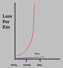
High signal attenuation. Although coaxial cables are an order better that twisted pair in terms of signal attenuation, this is achieved by an increase in bulk. Low-loss coaxial cables have diameters between 1 and 3 cm and become progressively more costly and unwieldy as the diameter increases. Further, loss is frequency dependent in copper conductors: the higher the data rate used, the higher the losses. In practice, transmitting data at rates beyond a few hundred Mbit/s is just not cost competitive. Whereas with fibre optic cables attenuation is virtually flat up to rates of several Gbit/s providing sufficient bandwidth for even the highest data rates as needed in the near future such as the 2.4Gbit/s SDH rate.

Figure 1 - Loss v. Frequency for Coaxial Cable
Interference sensitivity. Copper cables are prone to electromagnetic interference such as that created when switching on a piece of electrical equipment. This can create high error rates in data links (explaining why X.25 error correction protocol was developed). The reverse is also true, signals within the cable radiate from its entire length making it very easy to eavesdrop on what is being transmitted. In contrast, fibre optic cable can be laid next to power distribution cables and suffer no interference at all.
Ground loops. Copper cables by default provide an electrical link between source and destination and as such can cause problems. Ground potentials can vary by several volts between sites at different locations, say, two office blocks. If not handled correctly, this can cause high DC currents to flow which will cause random data errors (it can cause 50Hz hum on HI-FI as well). Electrical storms can also induce large currents in a copper cable which cannot only cause data errors but can cause severe physical damage as well. Being an insulator, fibre optic cables do not suffer from this problem.
A fibre optic cable consists of a glass silica core through which light is guided. This is covered with a material with a refractive index of slightly less than the core. This is called the cladding. The refractive index of the cladding need only be around 1% less than the core to achieve the total internal reflection necessary to confine the light to the core (Figure 2).

Figure 2 - Fibre Optic Total Internal Reflection
Although it was stated earlier that the real benefit of fibre optic cable over copper was virtually infinite bandwidth, there are effects that limit the achievable bandwidth and the length of the cable that can be used before the need of a repeater.
Attenuation
Transmission of light by fibre optics is not 100% efficient. There are several reasons for this including absorption by the core and cladding (caused by the presence of impurities) and the leaking of light from of the cladding. When light reflects off the cladding /core interface it actually travels for a short distance within the cladding before being reflected back. This leads to attenuation (signal reduction) by up to 2db/Km for a multi-mode fibre. For example, with this level of attenuation, if light travelled over 10kM of cable only 10% of the signal would arrive at the following end.
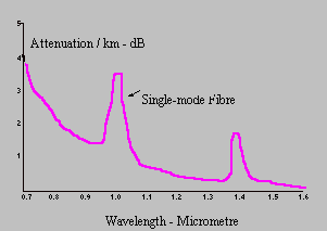
The amount of attenuation for a given cable is also wavelength dependent. Figure 3 shows the attenuation profile for the two main types of fibre; multi-mode and single-mode cable (described in detail below). The absorption peak at 1000nm is caused by the peculiarities of single mode fibre while the peak at 1400nm is caused by traces of water remaining in the fibre as an impurity. Due to this water absorption peak there are two standard single-mode wavelengths in use, 1310nm and 1550nm. 1310nm has been a standard for many years, only now is there a trend towards using 1550nm brought about by the need to extend the distances between repeaters.

Figure 3 - Fibre Optic Loss as a Function of Wavelength
Modal Dispersion
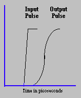
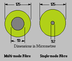
An optical fibre is a form of waveguide (as encountered with microwave radio transmission) and light can travel through it in a stable number of ways or modes. This needs a little explanation as it is an important concept. A light ray entering a fibre at a specific angle will travel through the fibre with a specific number of hops or reflections following a particular path. If the angle of the light ray entering the fibre changes slightly it is possible that the light will follow a different path with fewer, or maybe more, hops or reflections. The greater the diameter of the core the more modes exist and thus there are more ways the light can travel through the fibre. This type of fibre is called multi-mode. As light rays travelling in each mode will travel a different distance they will arrive at the output at different times. This effect is called modal dispersion and is measured in picoseconds per nanometre per kilometre, or ps/nm/km. In practice it means that a step-edge light pulse will be severely degraded by the time it reaches the output as shown in Figure 4. Put simply, dispersion limits the bandwidth of a fibre because as the data rate increases there is insufficient time for a logical '0' to recover to a logical '1' and vice-versa so the receiver is unable to differentiate between them. To reduce dispersion distortion, the number of modes the fibre supports must be reduced. This is achieved by reducing the diameter of the core as shown in Figure 5.
As the core of the fibre is reduced in diameter the situation is eventually reached where a light ray can only travel through the fibre via one path i.e. all light entering the fibre will traverse exactly the same path through the fibre before exiting at the same time - this is called a single-mode fibre. Because of this, the bandwidth of a single-mode fibre is much higher than that of a multi-mode fibre.

Figure 4 - Dispersion Distortion
The two main types of fibre in use today are step-index multi mode and step-index single mode fibre. The step-index part of the name can be understood by referring to Figure 5 which shows the cross-sections of these two types of fibre. Step-index refers to the abrupt change in refractive index between the core and cladding materials in contrast to graded-index fibres where refractive index changes gradually over the diameter of the fibre. Graded-index fibre will not be discussed here. Multi-mode fibres have cores of around 50µm and outside diameters of about 125µm. Single-mode fibre has a core reduced to below 10µm to allow only one mode of propagation to be supported.
Multi-Mode Fibre
Multi-mode fibre has the following characteristics:
The fibre can capture light from the light source and pass light to the receiver with high efficiency, so can be used with low-cost light emitting diodes (LEDs).
High precision connectors are not required because the large core diameter allows wide-tolerance on mechanics.
Low-cost comes at a cost! Multi-mode modal dispersion severely limits the usable bandwidth.
Multi-mode fibres suffer from higher losses than single mode fibres. For example, Mercury's Multimode fibre is specified at 0.8dB/km at a wavelength of 1310nm.
Multi-mode fibre has found some application in cost-sensitive areas such LAN (but even here it is too costly compared to copper solutions) and local-loop applications. But its poor bandwidth and high-loss characteristics has meant that its application in high-data rate PTO backbone links has been very limited. Indeed, with Mercury, only the original city fibre-optic network was deployed using multi-mode fibre. Since 1986, only single-mode fibre has been used.

Figure 5 - The Two Main Types of Fibre
Single-Mode Fibre
Single-mode fibre exhibits lower attenuation. Attenuation of Mercury's current single-mode fibre is specified at 0.37dB/km at 1310nm, in effect allowing a non-repeatered run to be increased by a factor of two over multi-mode fibre. The use of single-mode fibre completely eliminates modal-dispersion - the key cause of bandwidth limitation in multi-mode fibre optic fibre, but this does not mean that it has infinite bandwidth. What dispersion is left is called chromatic dispersion (so called as it is wavelength dependent). Chromatic dispersion is caused by the core material itself and is actually negative at short wavelengths and moves positive at longer wavelengths. This creates a 'magic' wavelength at which dispersion is actually zero.
This is, interestingly enough, at about 1310nm which explains the wide use of this particular wavelength (Figure 6). If 1310nm is used on a single-mode fibre it is easy to achieve a bandwidth of several Gbit/s with losses of around .37dB/km (Mercury's specification). Thus, in a single-mode fibre, attenuation is the limiting factor for long-distance transmission.
The characteristics of single-mode fibre are:
Bandwidth can be in the order of many Gbit/s with very low attenuation. This allows long-distance unrepeatered transmission up to around 50km.
The small diameter (10µm) of the core necessitates the use of expensive laser diodes to enable efficient light coupling and pass sufficient light into the fibre.
The small core diameter needs extremely precise connectors e.g. if two fibres are misaligned by only 1µm the overlap area is reduced by about 15% or attenuation equivalent to several km of fibre. Single-mode connectors are thus more expensive.
The performance of single-mode fibre is so good that it is the only type of fibre used for long distance links.

Figure 6 - Chromatic Dispersion in Single-Mode Fibre
Although the losses within silica based core materials are approaching theoretical limits, absorption by impurities keep them above those limits. Some impurities are inevitable as dopents need to be added to keep the refractive index of the core material above that of the cladding. A move was made to increase wavelength of the light source to 1550nm rather than use the more common wavelength of 1310nm. Indeed, this is what has happened, at a price. Attenuation drops from typically 0.35dB/km to 0.23dB/km, reducing attenuation by almost 35%. Looked at from another perspective, this equates to an increase in distance between repeaters in a long link from 50km to above 90km. In long links, the attenuation caused by splices becomes of more concern. Splices have typical attenuation values of 0.1dB which equates to around 0.4km of single-mode fibre!
Unfortunately, the price to be paid for lowered attenuation is an increase in chromatic dispersion. At 1310nm this is very near to zero, but at 1550nm it increases by a factor of six. Fortunately, even with that increase, it is still possible through careful system design to support the STM-16 SDH rates of 2.4Gbit/s over distances in excess of 100km.
A further way of reducing dispersion at 1500nm is to improve the quality of the laser-diode light sources used. Standard laser-diodes not only emit light at the primary or dominant wavelength but they also emit other wavelengths at the same time. These are close to the dominant wavelength but are at lower power levels. These sidelobes cause dispersion of digital signals being transmitted through a fibre optic fibre. Much work has gone into developing single-frequency lasers to minimise this effect.
Over the last few years fibre optic technology has advanced at a tremendous rate in a rather quiet and reserved manner driven by the need for higher bandwidths on long distance backbone links.
This performance enhancement has gone hand-in-hand with the development of suitable transmission and access methodologies such as SDH. The higher rates defined by SDH would not be possible without the improvements that have taken place in fibre optics.
Fibre optic technology is far from being plateaued. The next step will be coherent transmission systems that will improve the quality of fibre optic data transmission by at least an order of magnitude. In radio terms, it equates to the move from regenerative to superhet receivers and at the performance level it could be considered to equate to the move from PDH to SDH!